User Tools
Sidebar
Analog Cherry Keyboard Attempt 1
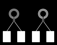
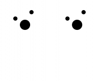
I made some rough sketches in Photoshop CS2 (yes Coil CB Designs in Photoshop). It worked out quite “good”, but it lacks some precision. I will have to try out something different (maybe Illustrator would work :thinking: out for this). Here are the three files I came up with. One for the traces (eg Coil and connection pads), one for the holes (the Cherry Key needs some holes in the CB, this also limits the size of the coil btw), and one for the outline (the cutout of the CB):
And also for people interested in the PSD-File:
The coil design you see is a special one and named planar coils. It is commonly used in microactuators or PCB motors. But I want to test if it works for my use-case also. The big plus point for this: I don't have to look into making a double-sided CB. Not so good is the number of windings I can do but maybe it will work out fine. It's still an experiment none the less. If you want to read more about this type of coils have a look into this: Electromagnetic Microactuators using Non-spiral Planar Micro coils for Robotic Applications
The pictures were converted for the milling machine with the help of fabmodules to the needed G-Code (.nc files).
The traces-picture needed the process “PCB traces (1/64)”. I just upped the cut speed to 10 mm/s and the tool diameter to 0.1 mm. The hole and outline-pictures needed the process “PCB outline (1/32)”. The cut speed was upped to 10 mm/s, the plunge speed to 5 mm/s, the jog height down to 2 mm, cut depth to 1.6mm, and the tool diameter up to 0.5mm. The traces (especially) on the left side are very fine. It was very hard to get these at least half-decently good into the CB with the CB-Milling Machine. Ferdi and I got it then after 3 passes for the traces.
As you may see we already did one pass before. The inconsistent color on the right coil shows that the bed of the machine is not perfectly level. From the first pass to the last pass, we were going down 0.05mm each pass. Here are the results:
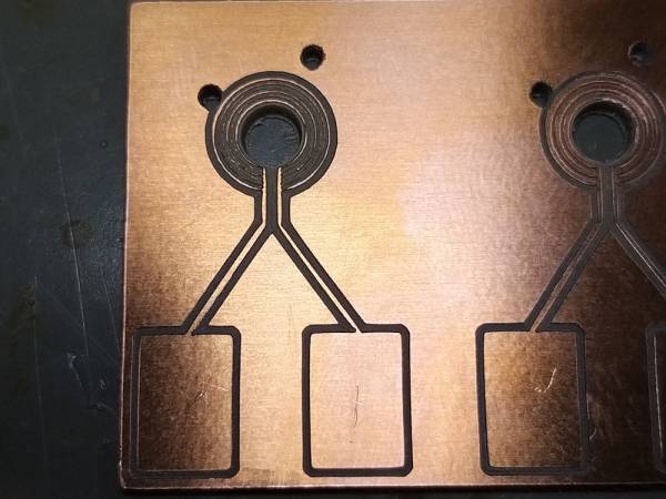
The left coil is designed with finner but therefore more windings. The problem right now there seemed to be a bit too far apart. The milling machine did two runs between two windings. Maybe I could get it to work with just one pass so that they be even narrower or I would have to make them even further apart. But with a multimeter, I can confirm that there is at least a connection between both pads.

The right coil looks a bit better. But it also has fewer coil turns and they are a bit more spaced apart. The spacing between the windings seems to be a bit more consistent. Also, there is some copper left between the windings. Hopefully, this can be scraped away later with a knife.
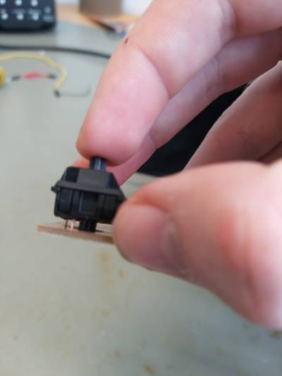
The holes came out well, at least their placing. Because the holes are not 100% straight and the middle one was a bit too small it did not fit well. This is mostly a problem in the middle one. This can be fixed in the next attempt.
After that, I just soldered some jumper cables to the pads. Now I have to make a circuit so I can measure the inductance of the coils.
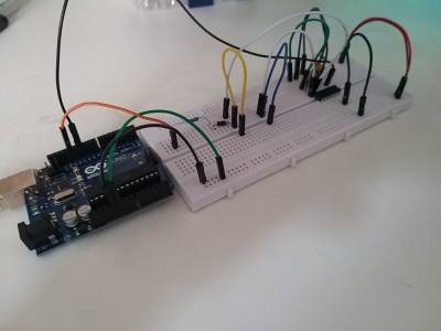
I tested out this circuit by electronoobs, but it was not working well and it is also not suitable for this kind of coils. The printed/milled out coils are just too small for this circuit. Also, the used wires were too long and made a lot of interference. As I found out I need a much higher frequency to measure the inductance of these coils (around 6 Mhz). Such a high frequency cannot be produced by an Arduino unfortunately. This project is somewhat close to what I need but I have to do more research on this. Until I make a new circuit I cannot test the coils if they even work.
Attempt 2

