User Tools
Sidebar
Table of Contents
Epilog Laser Fusion M2
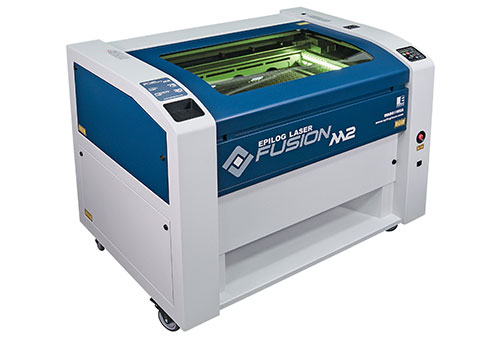
Arbeitsbereich 40“ x 28” (1016 x 711 mm)
Leistung: 60 Watt
Bedienungsanleitung
Maintenance
Epilog Fusion - Workflow
There are some basic and very important rules that you have to follow, before you start working with the Epilog Fusion Laser Cutter:
- Never leave the machine unattended. Many materials have the potential to suddenly burst into flames when cut with a laser – even materials that may be very familiar to the user. Always monitor the machine when it is operating. Especially during vektor cutting.
- Only cut materials that you can cut with the laser cutter. If you are not sure ask someone.
- Never forget to turn on the air compressor and filter, otherwise you might destroy the laser. Moreover after finishing a job wait a bit before you open the lid.
- Keep the area clear. Clean around the machine and keep the area free of clutter, combustible materials, explosives, or volatile solvents such as acetone, alcohol, or gasoline.
- Make sure you know what to do in case of fire.
How to place the Material
Place the material at a right angle. Moreover the area of the material being engraved or cut needs to be relatively flat.
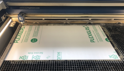
How to set the Jog
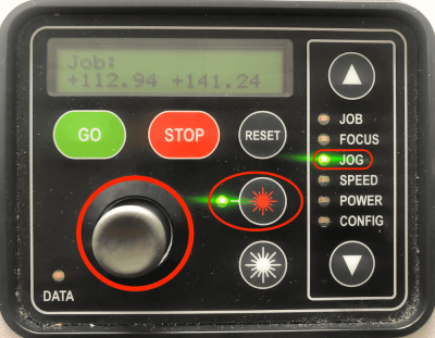
- Go to the Jog function on the Control Panel.
- Use the Joystick to move the carriage to a new position. Use the Red Dot Pointer as a visual indicator of the laser location. The display will also show a digital readout of the X and Y position.
- Confirm the position by pressing on the Joystick.
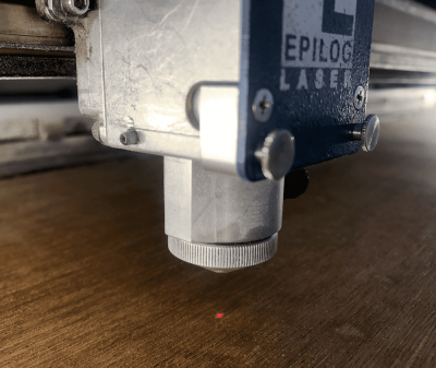
The Red Dot Pointer is the visual indicator of the laser location. This will be the new Home Position.
How to set the Focus
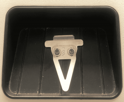
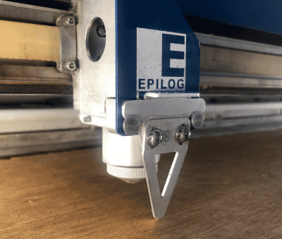
In order to engrave or cut a crisp, clean image, your material must be the correct distance from the bottom of the focus lens. To determine the correct distance use the “V” shaped manual focus gauge.
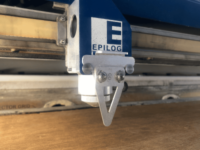
Place the manual focus gauge on the carriage. Then select the Focus on the control panel.
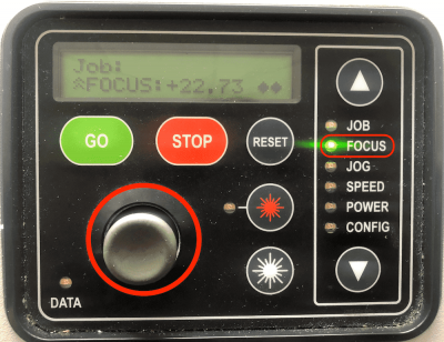
- Go to the Focus function on the Control Panel.
- Move the Joystick up or down to move the table appropriately until your material just touches the bottom of the gauge. The speed at which the table rises or lowers can be controlled by applying varying pressure upwards or downwards on the Joystick. Once the focus position has been established, remove the gauge.
- Confirm the position by pressing on the Joystick.
In the picture above the bottom of the focus gauge just touches the surface of the material.
How to start the Job
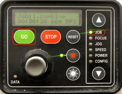
- Go to the Job function on the Control Panel.
- Press the Go key to start or resume a job.
- Pressing the Stop key will stop the lens carriage and the laser beam will be shut off.
- Pressing the Reset key will move the carriage to its home position.
Cutting Settings
| Material | Thickness | Speed | Power | Frequency | Application |
|---|---|---|---|---|---|
| Acryl | 3mm | 8 | 100 | 100 | Cut |
| Acryl | 5mm | 2 | 100 | 100 | Cut |
| Acryl | 6mm | 2 | 100 | 100 | Cut |
| Acryl | 9,5mm | 3* | 100 | 100 | Cut with SpeedComp* |
| Karton | 1,5mm | 400 | 50 | 20 | Cut |
| Karton | 1,5mm | 100 | 98 | 20 | Cut |
| Leder | 3mm | 35 | 100 | 50 | Cut |
| Holz | 3mm | 8 | 100 | 20 | Cut |
| Holz | 6mm | 5 | 100 | 10 | Cut |
| Holz | 9,5mm | 1 | 100 | 10 | Cut withSpeedComp* |
- The Fusion has two sets of Speed control for vector cutting applications. Checking the Speed Comp selection box in the print driver will reduce the speed setting you have selected by one half. Speed Comp is most useful for speeds of 1 to 10. Example: Cut a square at 5% speed. Then repeat the job at 5% speed and also select Speed Comp. The second square will take twice as long to cut as the first square. Speed Comp gives you more slower speed setting to work with. Always use Air Assist when cutting
Engraving Settings
| Material | Speed | Power | DPI/Freq. | Einsatz |
|---|---|---|---|---|
| Wood | 60 | 100 | 300 | Gravierung |
| Acryl | 90 | 45 | 300 | Foto Gravierung |
| Acryl | 90 | 65 | 300 | Vector Gravierung |
| Acryl | 90 | 60 | 600 | Vector Gravierung HiRes |
| Anodisiertes Aluminium | 90 | 40 | 400 | Foto Gravierung |
| Anodisiertes Aluminium | 90 | 35 | 600 | Foto Gravierung |
| Anodisiertes Aluminium | 90 | 45 | 600 | Vector Gravierung |
| Kork | 90 | 35 | 300 | Vector/Foto Gravierung |
| Glas | 90 | 35 | 300 | Vector/Foto Gravierung |
| Leder | 90 | 25 | 300 | Foto Gravierung |
| Leder | 90 | 30 | 600 | Vector Gravierung |
Rhino 5 - Tutorial
How to cut using Rhino
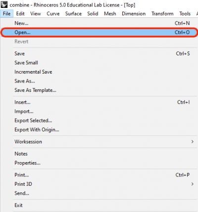
Go to File Open.. to import your Project in Rhino.
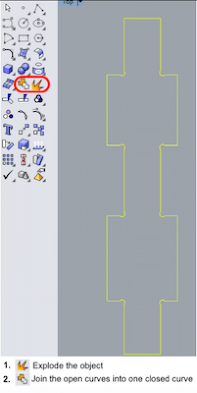
After importing the file, explode the objects and then connect the open curves to a closed curve.
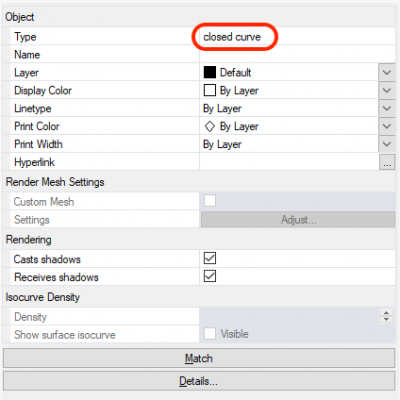
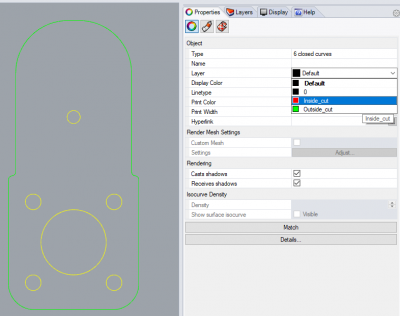
Then check in the Properties tab whether there are only closed curves.
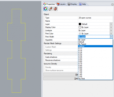
The laser determines which lines to engrave or cut based on the width (stroke) of each line. Set any cut lines to a print width of 0.001 or hairline.
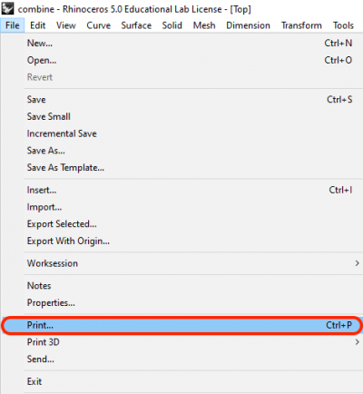
To start printing, press the Ctrl + P keys or go to File → Print.
Which Settings to set for a Print
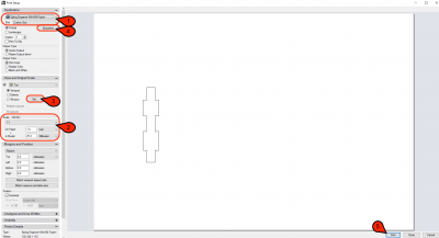
- Select the laser cutter you want to use for this job. In this cas it is the Epilog Engraver WinX64 Fusion and set the size to Costum Size
- Then make sure that the scale is set to 1:1.
- Now you can set the viewport.
- Next, configure the properties for the print.
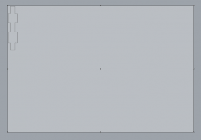
First adjust the viewport (point 3 above) by dragging it to its position. The starting point of the laser is always the upper left corner. To avoid wasting a lot of material, try to leave less free space around the objects.
Which Properties to set for a Print
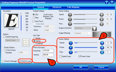
- Now select the Job type Vector.
Only select Send to Laser. You can now either keep the standard piece size settings (1016 x 711 mm) or costumize it to match it to the page size from your file. - Vector Settings:
The speed setting determines the travel speed of the carriage. The slower the speed, the deeper the cut. Slower speed settings will produce better edge quality.
The power settings determines the amout of laser energy that is delivered to the material. The higher the power, the deeper the cut. Power settings depend on the hardness and the thickness of the material.
The frequency is the number of laser pulses that the laser fires per inch of travel. A lower frequency will produce less heat, because fewer pulses are being used to cut. This is good for materials like wood. High frequencies are useful on materials like acrylic.
Speed Comp reduces all speed settings by 1/2. Power Comp reduces the laser output when the lens carriage slows as it moves through a curve.
After setting up everything you can start your job.
How to use Colormapping for inside and outside cut
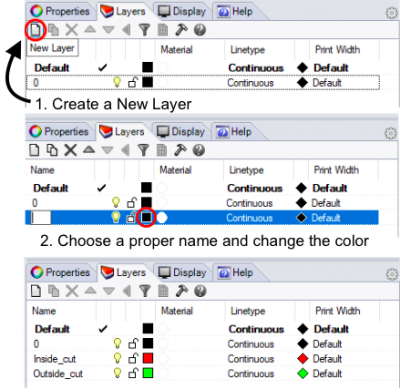
- Create a new Layer.
- Choose a proper name and color for this layer.
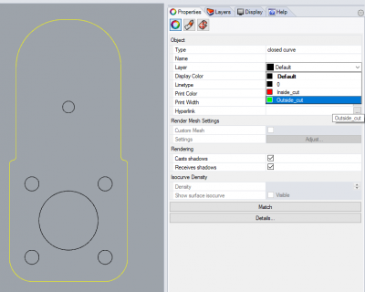
Change the layer for the shapes that are inside the object to separate them from the outer cut.
Select the outline of the object to change the layer to outer cut.
Using Color Mapping
To get started press the Ctrl + P Keys and go into properties.
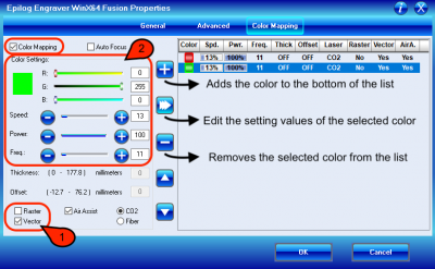
- Check the Color Mapping box in the upper left corner of the window. Now determine if it is a Vector or a Raster job.
- When color mapping is used it always starts from the top color in the Map list. So we always put the color of the inside cut first, in this case the color is red. Non-mapped colors will be processed last and will be processed using the speed and power setting from the General tab. Use the slider bars to create the same RGB color that you used in your design and set the laser parameters for this job. Then Add the color to the list. Check if the chronological order in the summary is correct.
After setting up everything you can start your job.
How to engrave a picture using Rhino
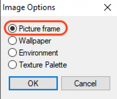
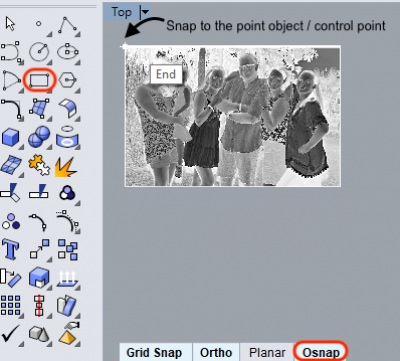
First of all drag and drop your picture into the Rhino working area to create a picture frame.
Now change the color of the default layer to white, to avoid getting the frame engraved as well.
Osnaps allow you to snap onto a specific object location when you are picking a point. Select it to create a fitting rectangle to cut out the image.
How to start a combined Job
To get started press the Ctrl + P Keys and go into properties.
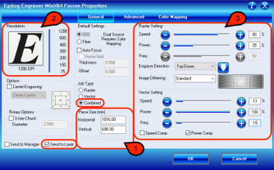
- Now select the Job type Combined. Combined is used when you want to incorporate both Raster and Vector. All Raster operations will be performed first, second the Vector operations.
- Only select Send to Laser. You can now either keep the standard piece size settings (1016 x 711 mm) or costumize it to match it to the page size from your file.
- The Resolution is expressed in dots-per-inches (DPI). It hereby defines the print quality. The higer the Resolution, the finer the detail that can be achieved. For fotos engravements you have to use a high DPI, since the details are very important. Note, that if you already have a picture with a low resoultion, setting the DPI to 600 or 1200, doesn't change this.
- Raster Settings:
- The speed setting determines the travel speed of the carriage. The slower the speed, the deeper the engraving. Speed settings depend on the hardness and the thickness of the material.
- The power settings determines the amout of laser energy that is delivered to the material. The higher the power, the deeper the engraving.
- Image Dithering: defines how the dot pattern will be engraved. The default mode is Standard. This mode can be used for all images including photographs. Jarvis and Stucki modes are designed to modify an image by replacing the very structured dot patterns with a more random dot pattern. Vector Settings:
- The speed setting determines the travel speed of the carriage. The slower the speed, the deeper the cut. Slower speed settings will produce better edge quality.
- The power settings determines the amout of laser energy that is delivered to the material. The higher the power, the deeper the cut. Power settings depend on the hardness and the thickness of the material.
- The frequency is the number of laser pulses that the laser fires per inch of travel. A lower frequency will produce less heat, because fewer pulses are being used to cut. This is good for materials like wood. High frequencies are useful on materials like acrylic.
- Speed Comp reduces all speed settings by 1/2. Power Comp reduces the laser output when the lens carriage slows as it moves through a curve.
After setting up everything you can start your job.
How to engrave Text or Shapes using Rhino
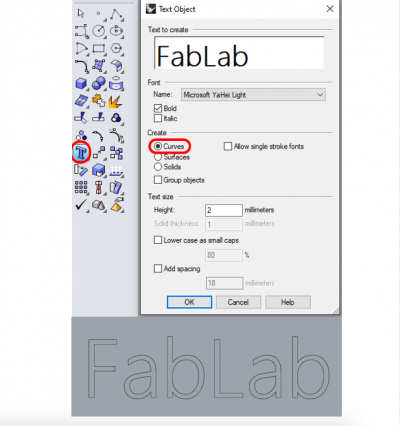
Create a Text object with Curves.
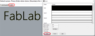
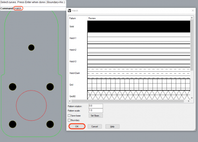
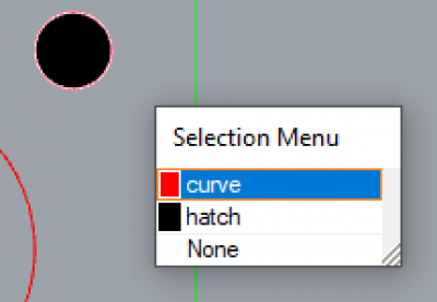
Next, search for Hatch on the command line. Select your Text and a solid pattern.
You can also use hatch to color shapes.
It is only important that you remove the curves, otherwise the laser might cut them when they are set to hairline.
How to start an engraving Job
To get started press the Ctrl + P Keys and go into properties.
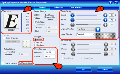
- Now select the Job type Raster.
Only select Send to Laser. You can now either keep the standard piece size settings (1016 x 711 mm) or costumize it to match it to the page size from your file. - The Resolution is expressed in dots-per-inches (DPI). It hereby defines the print quality. The higer the Resolution, the finer the detail that can be achieved. For fotos engravements you have to use a high DPI, since the details are very important. Note, that if you already have a picture with a low resoultion, setting the DPI to 600 or 1200, doesn't change this.
- Raster Settings:
The speed setting determines the travel speed of the carriage. The slower the speed, the deeper the engraving. Speed settings depend on the hardness and the thickness of the material.
The power settings determines the amout of laser energy that is delivered to the material. The higher the power, the deeper the engraving.
Image Dithering: defines how the dot pattern will be engraved. The default mode is Standard. This mode can be used for all images including photographs. Jarvis and Stucki modes are designed to modify an image by replacing the very structured dot patterns with a more random dot pattern.
After setting up everything you can start your job.
Inkscape
In inkscape you have to make sure that your cutting lines are thinner than 0.0254 mm
Instead of File –> print, you should use the “Win32 vector print”-addon:
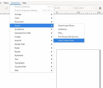
or save as pdf and print the pdf from Acrobat reader.
Working with the Epilog Job Manager
Using the Epilog Fusion laser cutter through the Epilog Job Manager brings to the user several advantages and automatize many steps in using the machine. In comparison of using the Epilog Fusion as a printer device in graphic design software, the Epilog Job Manager allows to the user to:
- Use the Auto Focus Function.
- Access and edit all the previous job that have been launched.
- Use a material library to automatically apply the proper settings.
- Visualize the preview of vector and raster output.
- Visualize and check the job position in relation to the machine bed.
- Send job(s) to machine.
- Categorize the jobs in folders, and to order them by time/name etc.
- Relaunch old job(s).
To start the Epilog Job Manager, just double-click on the icon in the Desktop:
Wether the job manager has been started or not, the driver of the Epilog Fusion keeps tracks of the job being sent from any other software. It is, anyway, not possible to create a job directly into the job manager. It is therefore needed to have your own design sent as a print job to the Epilog Fusion, before it appears in the job manager.
When printing something it is not necessary to change setting such as power, speed or frequency, because they will be set automatically into the Epilog Job Manager.
What is really important is to: Always set the resolution to 1200DPI before sending the job!
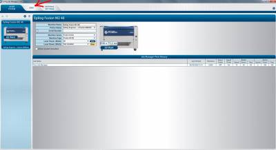
When opening the job manager, the following window will appear. To access the job that was sent to print just before, click on jobs.
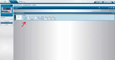
All the jobs sent by clicking on print in any other software, automatically go into the uncategorized folder. After clicking on Jobs, by default the list of uncategorized jobs will appear
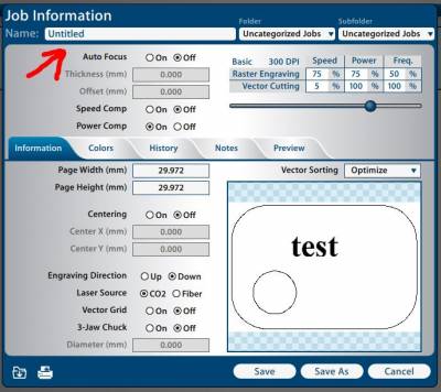
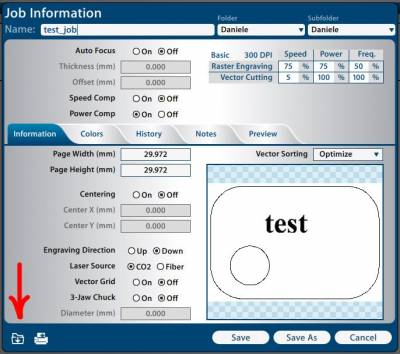
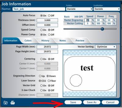
By double clicking on the job itself, it is possible to access to the job information window, where settings and properties of the job can be changed. For example it is possible to change the job name.
All the jobs sent by clicking on print in any other software, automatically go into the uncategorized folder. After clicking on Jobs, by default the list of uncategorized jobs will appear
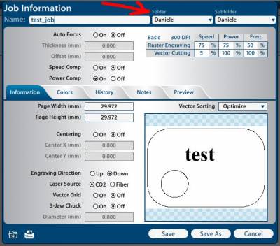
The job can be organized in folders and sub-folders. It is possible to set them by using their respective Drop-down lists. When a different folder is selected, the job will be automatically moved inside it.
The laser settings (speed, power, autofocus etc), can be changed for each job by manually changing the values, or it is possible to automatically set all of them by selecting a material from the material library. To open the material library and apply the settings click on the following button.
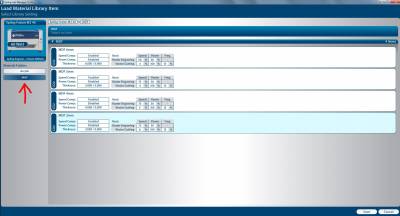
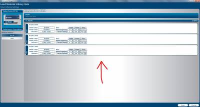
This will open the material library window. Like the jobs, the material library is organized in material folders, which contain then different materials sub-kinds and thicknesses. It is possible to change the material category by cliking on the left buttons.
Once the proper material category has been selected, it is possible to directly select the specific material just by double-clicking on it.
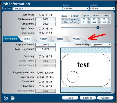
Once the material has been selected, the proper settings are automatically applied into the Job Information window (as shown in the next image). To be noted that also the material thickness is taken into account, meaning the Epilog Fusion will automatically adjust the focus. It is therefore not needed anymore to adjust the focus manually. To work with the colour mapping, settings can be changed by clicking the colours tab into the job information window. It is possible to check the job preview by clicking on the preview button.
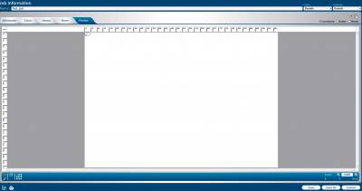
The preview window, shows the operation the laser cutter will do and the precise positioning of the job. Placing the stock into the shown position, will make sure the Epilog Fusion can work with it, and avoids the user to manually set the jog position. It is also possible to filter the view by operation kind /Raster/Vector/Combined).
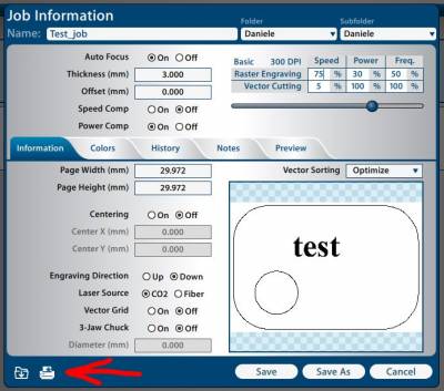
Once all the settings and the job properties have been applied/changed, it is possible to save the job for future reuse.
After saving the job, to send it the job to the Epilog Fusion, just click on the print button.
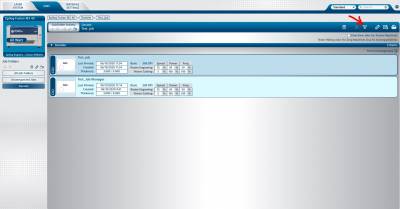
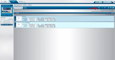
To manage the jobs, it is possible to change their appearance order clicking the following button.
Or to delete them from a specific folder clicking the delete button.
Fan on Full power
Dear Mr. Ingrassia,
if you experience fluctuations in laser power output after a certain time of operating the machine at near maximum or maximum power, that are not related to output position on the table, then this is usually the first sign of your laser tube beginning to fail. For example, if you experience material not being cut in a certain position on the table, pausing the machine for ~5-10 minutes, and then resuming the process with the material then being cut completely, this points to t failing laser tube. If the aforementioned case would yield not completely cut material even after a pause in the cutting process, something with table or beam alignment might be an issue.
There might be something you can try though. 30 minutes continuous power output at full power is not bad. If the tube is failing, you have detected it at a very early stage. Maybe you are simply having an issue with cooling of the laser tube body. Please make sure, that the filter located at the back of the machine is free from dust and lint, which might result in obstruction and reduced air flow. Epilog laser machines have a control board that allows to switch either to full cooling fan speed at all times and reduced cooling fan speed based on tube output power (not on actual tube temperature). Maybe this controller is not functioning correctly. Please try to switch the fan controller to full speed first. This provides additional cooling at all times, which inherently is a good thing. The only downside is more noise from the machine.
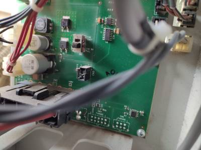
Depending on the build year of your machine, the controller is located somewhere in the lower compartment on the back side of the machine, either near the center or on the left side. Remove the screws holding the lower back panel in place and remove the panel, with the mains power disconnected. The laser tube is located at the right side of the machine, with power and signal cable going into the back of the tube. Follow the grey signal cable from the laser tube, that has RJ45-type plugs on both ends. This cable goes to a smallish board with four connectors in it, two being grey RJ45. On this board there is a small black sliding switch that allows you to change the operating mode of the fans (silent/full speed). If I have not previously advised you to change this to full speed, please switch the controller to full speed and check whether this has a positive impact on continuous laser output power.
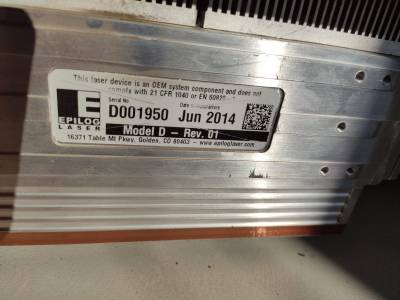
The laser tube still might be an issue, although increased cooling might mitigate the problem for another while. According to our machine log, the tube seems to still be the original one the machine was shipped out with in mid 2014. The average life expectancy of laser tubes without impairment of functionality in any way is around 7-8 years. The current age is 6.5 years, so problems might be expected now or in the near future.
Please let me know, if changing the fan mode helped you with the issues.
letztes mal Linse geputzt
29.3.2021 Markus

